


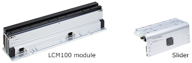
LCM100
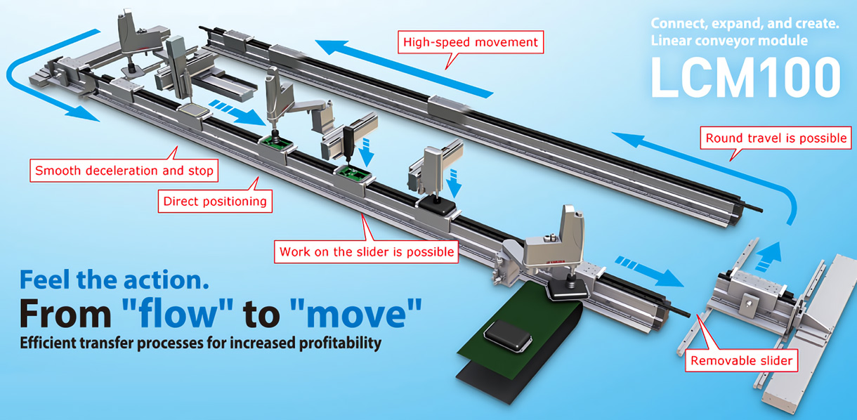
Linear Conveyor Modules LCM100
Next generation linear conveyor LCM100 supersedes belt conveyors and roller conveyors.
To all customers who have concerns regarding your production line
The issues facing the manufacturing industry continue to increase each year: shortened lead time, reduced cost, increased product quality, support for small production lots of diverse types, and reduced installation space.At a single stroke, the LCM100 solves these issues by fundamentally overturning existing concepts of transport between manufacturing processes. Why not implement the next generation of production line with us?
Two-second reduction in takt time. Here's why.
"Linear conveyor" overturns existing concepts of the production line.
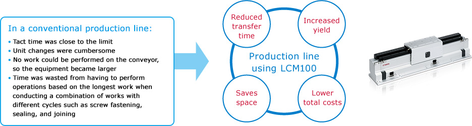
1. Reduced transfer time
Transfer takt time can be reduced simply by switching to the LCM100 linear conveyor in place of the free-flow conveyor or roller conveyor frequently used for transfer between manufacturing steps.
2. High-speed and high-accuracy transfer
-Max. speed: 3000 mm/sec.
-Max. acceleration: 2G
-Max. load mass: 15 kg
-Repeated positioning accuracy: +/−0.015 mm (standalone slider)*
*This is the repeated positioning accuracy for a standalone slider when positioning from one direction (single-side approach).
*The positioning accuracy for the single-side approach after correction by RFID is 0.1 mm including the mutual difference between sliders.
3. Increased yield
.gif)
Features and effectiveness of modular production.
Modular production allows highly flexible line structure.
The length of the transfer line can be adjusted freely by adding modules.
1. Save equipment space.
-Since the movement direction can be changed, the same processes are made common. This makes the equipment compact and results in cost reduction.
-Forward and backward movement at a high speed can be set freely.
-Flexible actions such as moving only some sliders backward is possible.
*Numerical values are used for setting transfer distance and stop positions
2. Can be moved efficiently between processes with different takts
-Narrow pitch movement is possible.
-Movement time can be reduced by combining the use of different movements, such as using pitch-feed for the same processes in short-time processes while transferring three workpieces at the same time at a high speed in long-time processes.
3. Workpieces do not need to be retracted
-As the work moves down, you can assemble and process them on the transfer line.
-Eliminates having to retract the work from the pallet to the work table.
-Reduces costs.
4. Significant reduction of start-up time
-Just connect modules for easy construction of a transfer line.
-Lifting cylinders, sensors, stoppers, and other complex parts are not necessary.
-Operations can be performed by using only the LCC140 Controller.
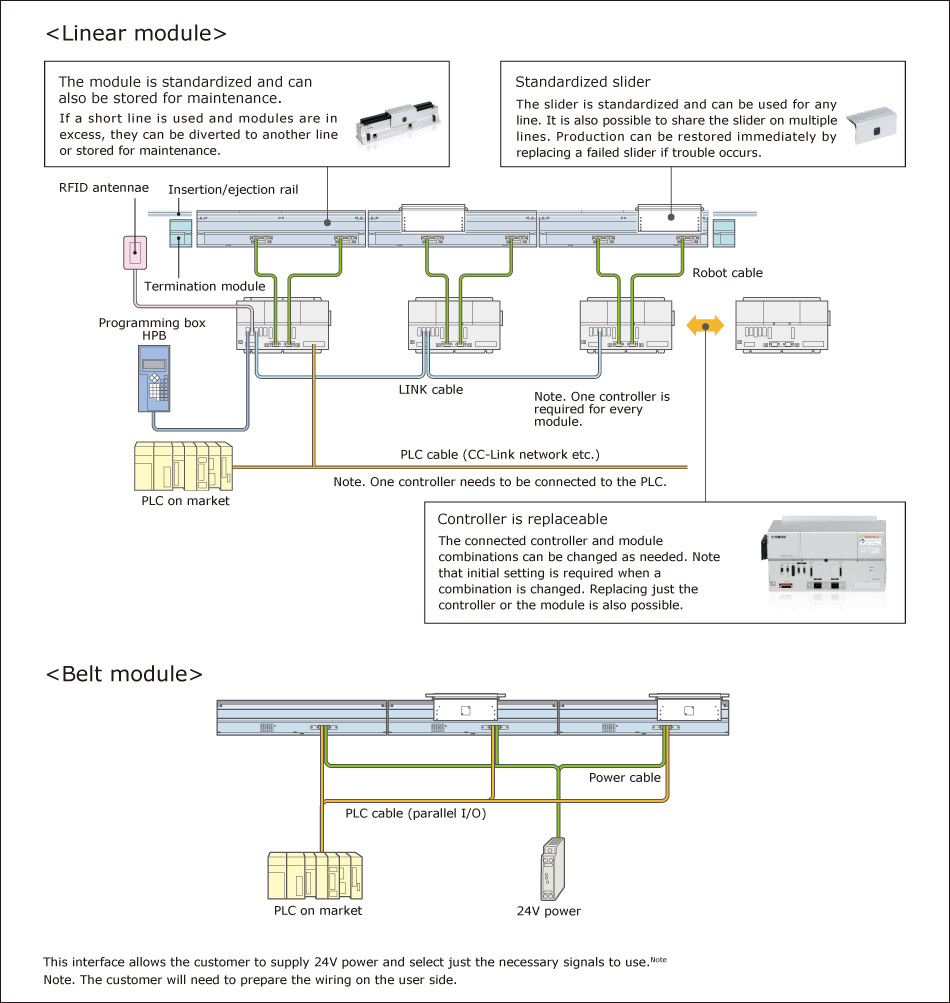
-Economical as excess modules can be used for other lines or stored for maintenance.
5. Construct branching lines, joint lines, and other lines in flexible configurations.
-Layout examples by combining modules with circulation mechanisms
Additional modules provide expandability.
A variety of modules for different needs are provided.
Flexible set-up of the slider's acceleration/deceleration, forward/backward movement, positioning, and other actions.The variety of possible line structures has been greatly expanded to supersede conventional models.
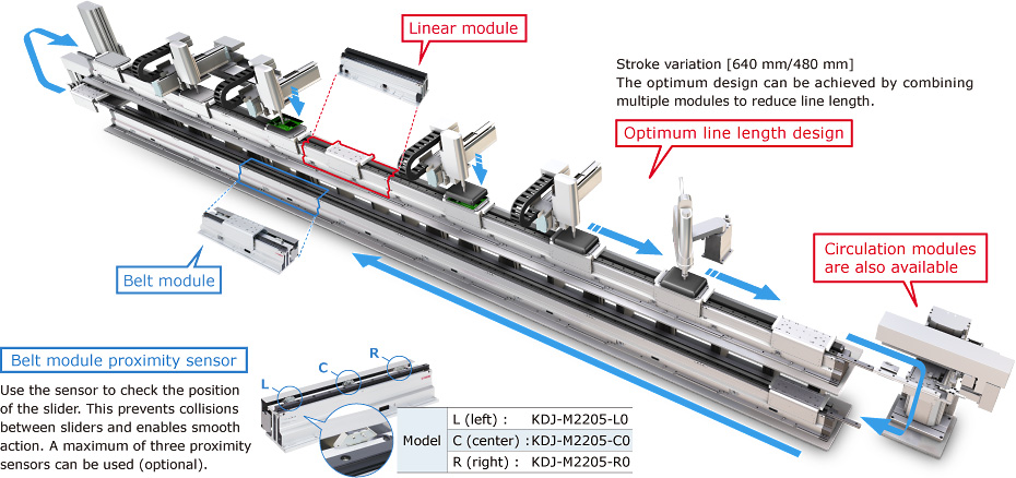
1. Belt modules can be selected to your needs
Genuine new Yamaha belt modules are included in the lineup.
-Low price...Using modules only for return processes and interprocess transfer will help reduce the facility cost.
-Easy control without controllers and no need to create robot programs
-Greatly decreased design and production labor
| Pin number | Signal | Role |
| A1 | +24V | Power connection |
| A2 | GND | DC24V(+/−10%) |
| A3 | ||
| A4 | Optional sensor L | Detection output |
| A5 | Optional sensor C | Detection output |
| A6 | Optional sensor R | Detection output |
| A7 | ALARM output | Alarm output |
| A8 | SPEED output | Speed output |
| B1 | ALARM-RESET input | Alarm reset input ON [L]:reset. OFF [H]:normal. |
| B2 | INT.VR/EXT input | Speed setting device switching input ON [L]:internal. OFF [H]:External. |
| B3 | CW/CCW | Rotation switching input ON [L]:CW. OFF [H]:CCW |
| B4 | RUN/BRAKE | Brake input ON [L]:run. OFF [H]:momentary stop. |
| B5 | START/STOP | Start/stop input ON [L]:run. OFF [H]:stop. |
| B6 | VRL | − side Speed setting current power |
| B7 | VRM | + side DC 0 − 5V 1mA or higher |
| B8 | VRH | (When a dedicated speed setting device used) |
The guide connections, connection height, and stroke length are completely compatible between belt and linear modules. Reduced design and production labor will help speed up the start-up time.*
*The belt module and the linear module have different depths.
2. Easier to design and implement
-LCM100-2MT, a module for circulation, is available to insert or eject a slider into or out of a line.
-Also can be used for a return mechanism.
Excellent maintainability.
Standardization of module structure and parts ensures easy part exchange and maintenance.
Loss-free transport that was not possible with conventional conveyors can be achieved with LCM100. Reduce losses while increasing profitability.
1. Optimal for small batch production of various product types
-No need for mechanical stoppers or sensors. Change layout easily.
-Reconstruction can be finished quickly by just changing the program to set a stop position.
-Frequent unit changes for different models can be handled flexibly.

2. Quick recovery by replacing the slider when machine trouble occurs
-Parts can be replaced easily.
-Parts can be kept for maintenance as they are standardized.
-Possible to minimize the downtime of a production line.
3. Easy maintenance
-Motors and scales do not make contact and are free from abrasion.
-As only the rails are sliding parts, dust generation is low.
-There are only a few consumable parts, which mean a long service life.

System configuration diagram (when 3 sliders are connected)
Static tolerable load of slider
Static loads shown below are tolerable as references when performing the screw tightening, part assembly, or light press-fitting on the slider.
 |
 |
 |
|||||||||||||||||||||||||||||||||||||||||||||||||||||||||||||||||||||||||||||||
|
FA
*The loads shown above are tolerable loads at a position "A" mm away from the center of the guide rail. |
FB
|
FC
*The loads shown above are tolerable loads at a position "C" mm away from the slider upper surface. |
|||||||||||||||||||||||||||||||||||||||||||||||||||||||||||||||||||||||||||||||
Basic specifications
| linear conveyor module | |
| Drive method | Moving magnet type, Linear motor with flat core |
| Repeat positioning accuracy |
+/−0.015 mm (single slider)* |
| Scale | Electromagnetic type / resolution 5 μm |
| Max. speed | 3000 mm/sec |
| Max. acceleration | 2 G |
| Max. payload | 15 kg***/**** |
| Rated thrust | 48 N |
| Total module length | 640 mm (4M) / 480 mm (3M) / 400 mm (for 2MT circulation) |
| Max. number of combined modules | 16 (total length: 10240 mm) |
| Max. number of sliders | 16 (when 16 modules are combined) |
| Min. pitch between sliders | 420 mm |
| Mutual height difference between sliders | 0.08 mm |
| Max. external size of body cross-section | W 136.5 mm × H 155 mm (including slider) |
| Bearing method | 1 guide rail / 2 blocks (with retainer) |
| Module weight | 12.5 kg (4M) / 9.4 kg (3M) / 7.6 kg (2MT) |
| Slider weight | 2.4 kg / 3.4 kg (when the belt module is used.) |
| Cable length | 3 m / 5 m |
| Controller | LCC140 |
* Repeated positioning accuracy when positioning in the same direction (pulsating).
** Positioning accuracy in the pulsating when using the position correction function with the RFID.
*** Weight per single slider.
**** When used together with the belt module, the max. payload becomes 14 kg since the parts dedicated to the belt are attached to the slider.
| belt module | |
| Drive method | Belt back surface pressing force drive |
| Bearing method | 1 guide rail / 2 blocks (with retainer) |
| Max. speed | 560 mm/sec |
| Max. payload | 14 kg |
| Module length | 640 mm (4B) / 480 mm (3B) |
| Max. number of sliders | 1 slider / 1 module |
| Main unit maximum cross-section outside dimensions | W 173.8 mm × H 155 mm (including slider) |
| Cable length | None |
| Controller | Dedicated driver (Included) |
| Power supply | DC 24 V 5A |
| Communication I/F | Dedicated input/output 16 points |
| Module weight | 11.2 kg (4B) / 8.8 kg (3B) |
| LCC140 (controller for LCM 100) | |
| Controllable robot | Linear conveyor module LCM series |
| Outside dimensions | W402.5×H229×D106.5mm |
| Main body weight | 4.8 kg |
| Input power voltage | Single-phase AC200 to 230V +/−10% or less (50/60Hz) |
| Maximum power consumption | 350VA (LCM100-4M 1 slider is driven.) |
| External input/output |
-SAFETY |
| Network option |
-CC-Link Ver. 1.10 compatible, Remote device station (2 stations) |
| Programming box | HPB, HPB-D (Software version 24.01 or later) |
Catalog
-LCM100 Catalog (2.8 MB)
-Linear conveyor module (640mm/480mm) (341 KB)
-Module for circulation (2MT) (341 KB)
-Belt module (640mm) (341 KB)
-Belt module (480mm) (341 KB)
-Belt module slider (381 KB)